ESP32-CAM Beginner’s Guide
The ESP32-CAM is an amazing small module and it’s full-featured microcontroller that has an integrated video camera and microSD card socket.
In this article I’ll guide you through the basic specifications and my own project. So, if you continue reading, you’ll learn how to turn ESP32-CAM module into IP camera. Let’s begin!
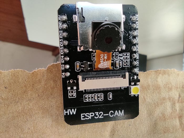
It’s the inexpensive module that is easy to use. ESP32-CAM is perfect for IoT devices requiring a camera with advanced functions like image tracking and recognition or just video streaming.
ESP32-CAM pinouts:
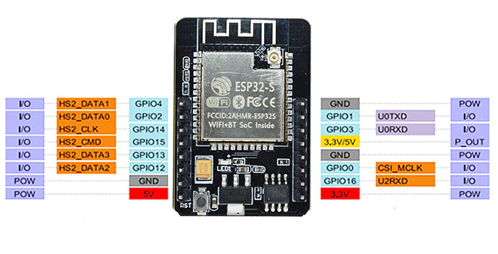
ESP32-CAM Specifications
The ESP32-CAM is based upon the ESP32-S module, so it shares the same specifications. It has the following features:
- 802.11b/g/n Wi-Fi
- Bluetooth 4.2 with BLE
- UART, SPI, I2C and PWM interfaces
- Clock speed up to 160 MHz
- Computing power up to 600 DMIPS
- 520 KB SRAM plus 4 MB PSRAM
- Supports WiFi Image Upload
- Multiple Sleep modes
- Firmware Over the Air (FOTA) upgrades possible
- 9 GPIO ports
- Built-in Flash LED
Camera Specifications
The ESP32-CAM includes an OV2640 camera module. The device also supports OV7670 cameras. The OV2640 has the following specifications:
- 2 Megapixel sensor
- Array size UXGA 1622×1200
- Output formats include YUV422, YUV420, RGB565, RGB555 and 8-bit compressed data
- Image transfer rate of 15 to 60 fps
Wiring diagram for ESP32-CAM
In order to upload sketch you will need FTDI adapter. Here you can see a wiring diagram.
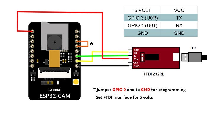
However, it’s important to note that FTDI adapter must be set to 5 volts, in this case. In many tutorials you will find that FTDI is set to 3.3 volts but it’s not working for me. I’m not able to run ESP32-CAM with 3.3 volts and it gives me “Brownout detector was triggered” error.
Programming with the Arduino IDE
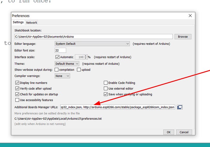
Firstly, you’ll need to use the Board Manager to add ESP32 boards. You can do it by adding a JSON file link to your Arduino IDE Preferences “Additional Boards URL” text box.
- Open the Arduino IDE.
- Click on the File menu on the top menu bar.
- Click on the Preferences menu item. This will open a Preferences dialog box.
- You should be on the Settings tab in the Preferences dialog box by default.
- Look for the textbox labeled “Additional Boards Manager URLs”.
- If there’s already text in this box add a coma at the end of it, then follow the next step.
- Paste the following link into the text box — https://raw.githubusercontent.com/espressif/arduino-esp32/gh-pages/package_esp32_index.json
- Click the OK button to save the settings.
The textbox with the JSON link in it is illustrated here:
After that, you will need to use the new entry to actually add the ESP32 boards to your Arduino IDE. You do that by following this procedure:
- In the Arduino IDE click on the Tools menu on the top menu bar.
- Scroll down to the Board: entry (i.e. Board: Arduino/Genuino Uno).
- A submenu will open when you highlight the Board: entry.
- At the top of the submenu is Boards Manager. Click on it to open the Boards Manager dialog box.
- In the search box in the Boards Manager enter “esp32”.
- You should see an entry for “esp32 by Espressif Systems”. Highlight this entry and click on the Install button.
- This will install the ESP32 boards into your Arduino IDE
If you go back into the Boards: submenu you should now see a number of ESP32 boards.
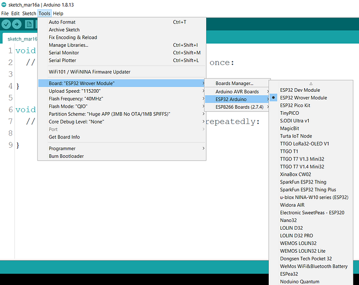
You’ll need to select the board that matches (or is equivalent to) the ESP32 board you have purchased.
Let’s try our first sketch
The sketch we will be testing is the CameraWebServer sketch. You can load it as follows:
- Open the Arduino IDE
- Click on the File menu item on the top menu bar.
- Scroll down and click on Examples. A sub-menu will open.
- Scroll down the sub-menu and look for Examples for A-Thinker ESP32-CAM.
- Below this you’ll see an entry for ESP32. Click on it and another sub-menu will open.
- Select Camera from this sub-menu.
- Select CameraWebServer.
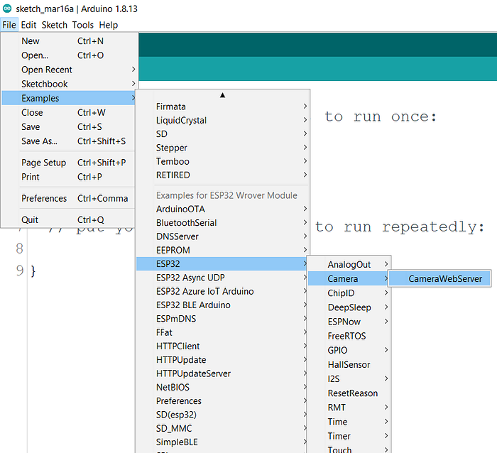
The sketch turns the ESP32-CAM into a full-featured online camera, options like face detection and a bunch of other controls. It’s a very good demonstration of the ESP32-CAMs capabilities!
In the sketch you should type your WiFi SSID and password.

Before you hit the button for uploading sketch, choose the right options for your board. Here’s the example of what’s working for me:

Be sure you have the jumper connected between GPIO 0 and Ground!
When uploading is finished remove the jumper wire between GPIO 0 and GND and press the reset button on the ESP32-CAM module.

Open serial monitor and you will see IP address of the camera. After you open it, you’ll see something like this:
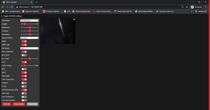
That’s it! Do you like this tutorial? Give it a clap!
Thanks for reading and good luck with your project!
